Flex Circuits, RIGID-FLEX Capabilities
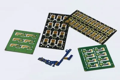
A Flex PCB or FPCB is a patterned arrangement of printed circuitry and components that utilizes flexible based material with or without flexible coverlay. These flexible electronic assemblies may be fabricated using the same components used for rigid printed circuit boards, but allowing the board to conform to a desired shape (flex) during its application. Experience cutting-edge solutions with Precisio PCB, your top-tier partner for flex and rigid-flex PCB manufacturing in the USA.
From quick-turn flex to rigid-flex circuits or any PCB type, our capabilities, equipment, and expertise ensure your needs are met. Benefit from flex circuit services for PCB layout, fabrication, and assembly, tailored to your requirements. Contact us today for flex circuit parts for your products.
Precision PCB flex material selections
- Polyimide Films:- 0.5 mil (.0005″), 1 mil (.001″), 2 mils (.002″), 3 mils (.003″), 5 mils (.005″)
- Thermobond Adhesives:- Acrylic/Modified Acrylic, Phenolic Butyral, Modified Epoxy
- Copper Foils (rolled-annealed):- 1/4 oz , 1/3 oz, 1/2 oz. (.0007″), 1 oz. (.0014″), 2 oz. (.0028″)
- Stiffeners:- FR-4, polyimide, metal, or customer supplied
- FR-4 in Multi-layer Flex Circuits:- Laminated to flex circuit to create rigid flex boards. Typically with vias.
- Surface Finish:- Solder (hot air leveling or electrolytic plating), Electroless Au and Ni, Silver, Tin plating
Fabrication Tolerances
- Minimum Trace to Route Edge Dimension+/- .005″
- Minimum Route Dimensional Tolerance+/- .005″
- Minimum Tolerance of ZIF Connector to Edge of Flex+/- .002″
- Minimum Feature to Feature Dimensional Tolerance+/- .002″
- Minimum Corner Route Radius.010″ +/- .0005″
- Minimum Inside Radius.006″ +/- .0003″
Artwork Capabilities and Tolerances
- Minimum Trace and Space: .002″/.002″ (1/4 oz.) .003″/.003″ (1/2 oz.)
- Minimum Annular Ring Over Drill Size: .014″
- Required on Artwork to Maintain Tangency: .010″ (GERBER required)
- Minimum Inner Diameter or Thermal Reliefs: .006″ (drill size)
- Minimum Space Between Coverlay Openings: .010″
- Edge of Coverlay Opening to Trace: .007″ (preferred).
- Minimum Legend Line Width: .007″
Miscellaneous
- Minimum Layer to Layer Registration+/- .005″
- Drill Position Accuracy+/- .003″
- Average Copper Plating Tolerance (PTH only).001″ +/- .0005″
- Average Solder Plating Thickness.0003″
- Squeeze out of 1 mil Adhesive and 2 mil Adhesive.003″ +/- .001″ .006″ +/- .003″
Drill Capabilities
- Smallest Drill Size: .006″ mechanical .002″ laser
- Largest Drill Size: .267″
- Smallest Slot Width: .008″